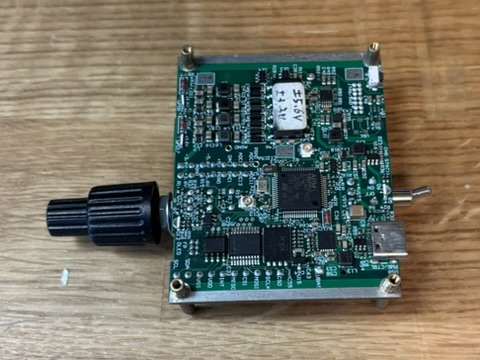
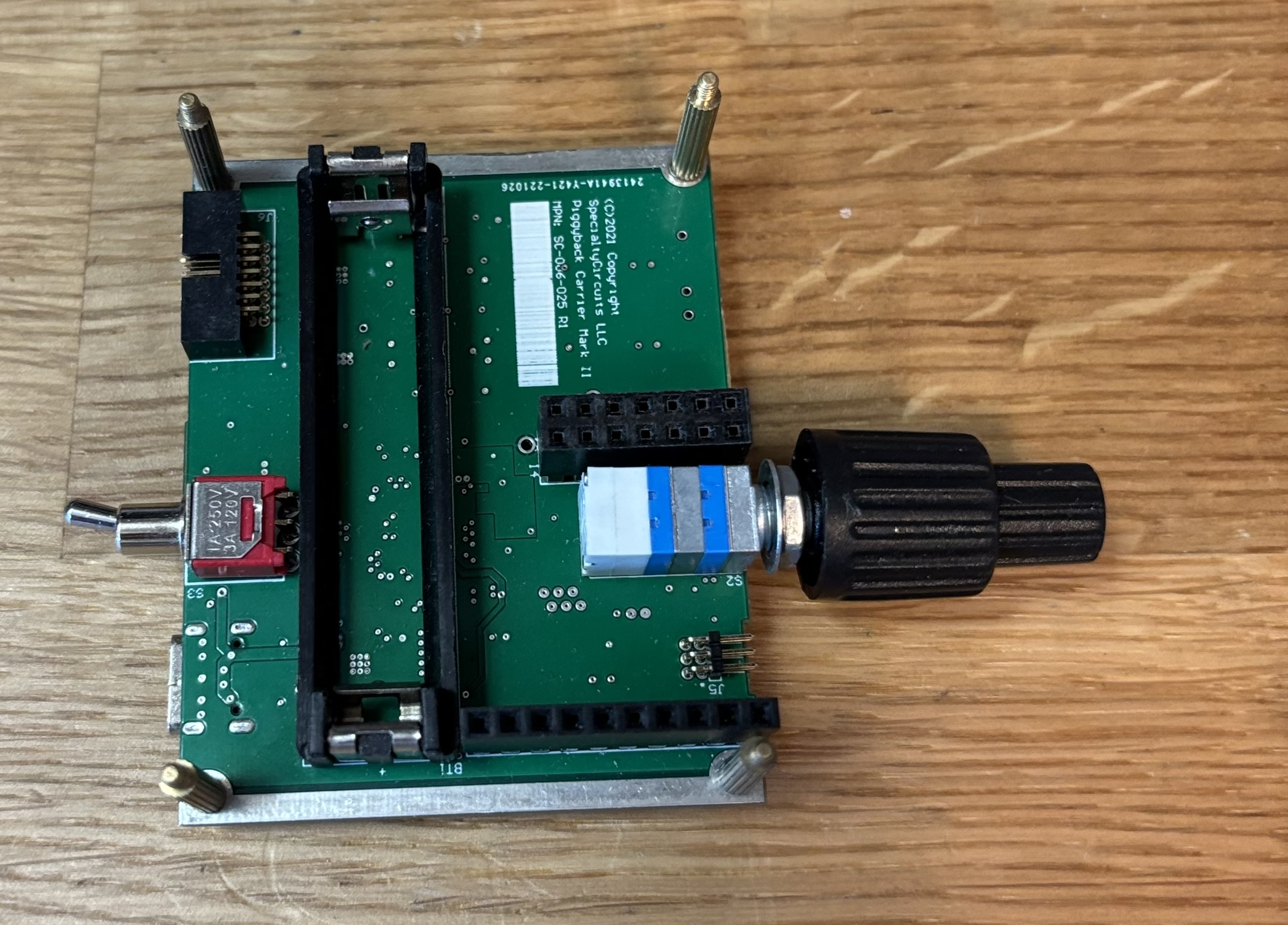
Piggyback Base Carrier

At SpecialtyCircuits, we produce many types of amplifier for oscilloscope or signal
sensing applications. A common need of a universal bipolar power source and digital communication interface starts to rise. To minimize repeated development effort on creating functionally similar power and digital circuitry, we created Piggyback Carrier board together with matching enclosure and standardized front panel designs.
Application:
- Powering ultra-low noise amplifier
- Battery powered amplifier
- Platform for oscilloscope active probe head
- Powering isolated small signal digitizer
- Powering isolated analog control
- Platform for analog components testing module
Highlight:
- 1W total +/-6V and +/-14V unregulated quad low noise power outputs.
- Isolated and slew-rate controlled switching DC converter, eliminating ground loop and switching transient.
- USB Type-C power entry. Configurable for 500mA or 900mA max current.
- Optional built-in rechargeable lithium-ion battery (14250, 1/2AA) and charger.
- Optional built-in micro-controller for host PC side control.
- Optional isolated SPI and I2C bus for digital control peripheral ICs.
- Optional concentric dual rotary encoder knob and switch for manual control.
A summary of key feature includes:
Isolated DC/DC converters are included to generate necessary voltages for analog daughterboard. The DC ground path of USB power input is completely removed by the isolated DC/DC converter.
An optional built-in 300mAh 14250 lithium ion battery is designed in as a way to eliminate addition ground path from USB power input, if that is still a concern with isolated DC/DC converter.
Four filtered switching power outputs covering +/-6V, and +/-14V. Low parasitic capacitance push-pull transformers are selected to step the voltage of 3.6-4.2V lithium-ion battery output to desired voltages. Slew rate limited transformer driver ICs are selected to minimize switching transients. Additional ferrite bead and pi filters are employed to further attenuate switching transient and ripple.
STM32 series microcontroller was added to the board to support digital control of add-on boards. The firmware can be flashed/update via USB communication. A JTAG header is also provided for user firmware development.
A few front panel LEDs are included to indicate the status of the Piggyback devices. There are indication for USB power good, battery charging state, analog power ready and an RGB LED controlled by microcontroller internal program.
A user power switch is provided on the back panel of the box. There are primarily three purpose, one is to power off the device the second is to power of the analog session so that battery charging can utilize the full 300mA current draw from USB power. The third is for user to observe signal change on oscilloscope between power on/off to distinguish noise floor of oscilloscope and the Piggyback devices.
An SPI bus and an I2C bus are provided through digital isolators. The speed of SPI bus is limited by STM32 operation frequency, not by the digital isolator. Six wires are allocated for SPI bus, two of them are chip select chips, and one is to pass interrupt event back to the microcontroller.